

Deployment Method Selection Guide
Overview
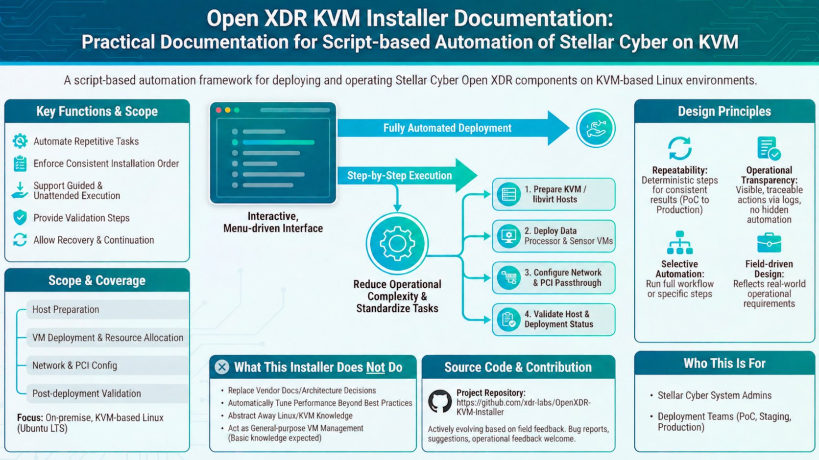
This guide compares deployment models for the Stellar Cyber OpenXDR Platform based on infrastructure, performance needs, and operational constraints. Rather than focusing on the installer’s internal implementation, it is intended to help operators decide:- which installer to use
- which network mode or attachment method to select
- how to balance performance, stability, and day-to-day simplicity
- bare-metal server deployments
- virtualized or private-cloud environments
- Data Processor (DP), Sensor, and AIO deployment scenarios
Recommended Configuration by Deployment Environment
Detailed Deployment Decision Criteria
1. Bare-Metal Server Deployment
1.1 Data Processor Deployment
Three or more physical servers (cluster deployment)
When deploying Data Processors across three or more physical servers, install each server individually according to the Data Processor Installer guide. Recommended approach:- configure all servers as a DP cluster
- use Configuration → Cluster Interface Mode
- set Cluster Interface Mode to SR-IOV
Why SR-IOV is recommended
- each DP node communicates directly through the physical NIC
- cluster traffic bypasses the virtual-switch layer
- inter-node latency is minimized
- provides the highest practical cluster performance
Two-node server cluster
There are two recommended approaches depending on the network design.When a 10GbE switch is available
- set Cluster Interface Mode to SR-IOV
- connect both servers to the switch
- high throughput
- a topology that can be expanded later
When no switch is available (direct connection)
- set Cluster Interface Mode to Bridge
- directly connect the two servers using high-speed NICs
- one node acts as the Master
- the second node acts as a Worker or Warm Standby
- a simple switchless topology is required
1.2 Sensor Deployment on Bare Metal
When deploying a Sensor on a bare-metal server:- follow the Modular Sensor Installer guide
- deploy the Sensor directly on physical hardware to maximize available resources
- attach SPAN NICs using PCI Passthrough
- this is the default and recommended method
Key characteristics
- each SPAN NIC is passed directly to the Sensor
- no virtual-switch overhead is introduced
- maximum packet capture and processing performance is available
- the NICs support PCI passthrough
- sufficient hardware resources are available
2. Deploying AIO and Sensor on a Single Server
When hardware resources are limited, AIO and Sensor can be deployed together on one physical server. Recommended procedure:- follow the AIO & Sensor Installer guide
- deploy both components on the same host
Important performance considerations
The following configuration is technically possible:- allocating more vCPUs than are available on NUMA node 0
- skipping CPU pinning
- allowing AIO to use CPUs across multiple NUMA nodes
- memory access crosses NUMA boundaries
- latency increases
- overall system performance can degrade
Recommendation
- keep AIO CPU allocation within a single NUMA node
- use CPU pinning whenever possible
- use multi-NUMA allocation only as a last resort
3. Deployment in Virtualized or Private-Cloud Environments
In private-cloud or virtualized environments, direct access to physical hardware is commonly restricted.3.1 Data Processor Deployment
When deploying a Data Processor in a virtualized environment:- follow the Data Processor Installer guide
- set Cluster Interface Mode to Bridge
Why Bridge mode is required
- physical NIC passthrough is often unavailable
- SR-IOV may be restricted or unsupported
- Bridge mode allows DP nodes to communicate over the virtual network
Example architecture
- deploy DL Master on one KVM host
- deploy DA Master on another KVM host
- connect the two nodes using an L2 bridge
3.2 Sensor Deployment in a Virtualized Environment
For Sensor deployment:- follow the Modular Sensor Installer guide
- configure SPAN NICs in Bridge mode
- trades some absolute performance for flexibility
- works reliably where PCI passthrough is unavailable
- fits private-cloud, test, and regulated environments
3.3 AIO + Sensor Deployment
The standard AIO & Sensor Installer Auto Execute workflow deploys both AIO and Sensor.- management networking uses NAT mode
- Sensor SPAN attachment uses PCI Passthrough
- therefore this path may not be appropriate for private clouds that do not expose physical PCI passthrough
4. Sensor-Only Deployment Options
Network separation for security or operations
Some environments require the Sensor VM network to be separated from the KVM host network for:- security isolation
- day-to-day visibility
- management-policy compliance
- follow the Modular Sensor Installer guide
- set Sensor Network Mode to Bridge
- the Sensor VM to use a dedicated physical interface
- the KVM host to keep a separate management network
- clear separation between management traffic and Sensor traffic
The default Sensor network mode is NAT.
5. Network Terminology
This section explains the primary network terms used throughout the installer and deployment guides.Bridge Mode (Sensor)
Bridge mode connects a virtual machine directly to a physical or virtual network at Layer 2. In simple terms:- the VM behaves like a physical server on the same network
- it has its own MAC address
- traffic flows without address translation
When to use it
- high-performance networking
- clear network separation
- direct server-to-server communication
NAT Mode (Data Processor, AIO, Sensor)
NAT (Network Address Translation) mode places the VM behind the KVM host. In simple terms:- the VM uses an internal private IP address
- the host acts as the gateway
- external systems see the host IP address
When to use it
- simple deployment environments
- environments with limited IP address resources
Trade-offs
- simpler configuration
- additional access and management considerations
PCI Passthrough (Sensor)
PCI passthrough assigns a physical NIC directly to a virtual machine. In simple terms:- the VM controls the NIC directly, similar to bare metal
- no virtual switch or host network stack is in the traffic path
- near-native performance is available
When to use it
- high-throughput Sensor deployments
- SPAN or mirrored-traffic collection
- bare-metal or dedicated-hardware environments
SR-IOV (Data Processor)
SR-IOV (Single Root I/O Virtualization) allows one physical NIC to be divided into multiple virtual NIC functions. In simple terms:- one physical NIC is divided into multiple lightweight virtual interfaces
- each virtual interface can be assigned to a VM
- performance is higher than Bridge mode, but operational complexity is also higher
When to use it
- Data Processor cluster interfaces
- high-performance multi-node cluster communication
- environments where the hardware and BIOS support SR-IOV